**Final project report**
(#) Student 1 Wenxuan Xu f007fsy
(##) Motivational image
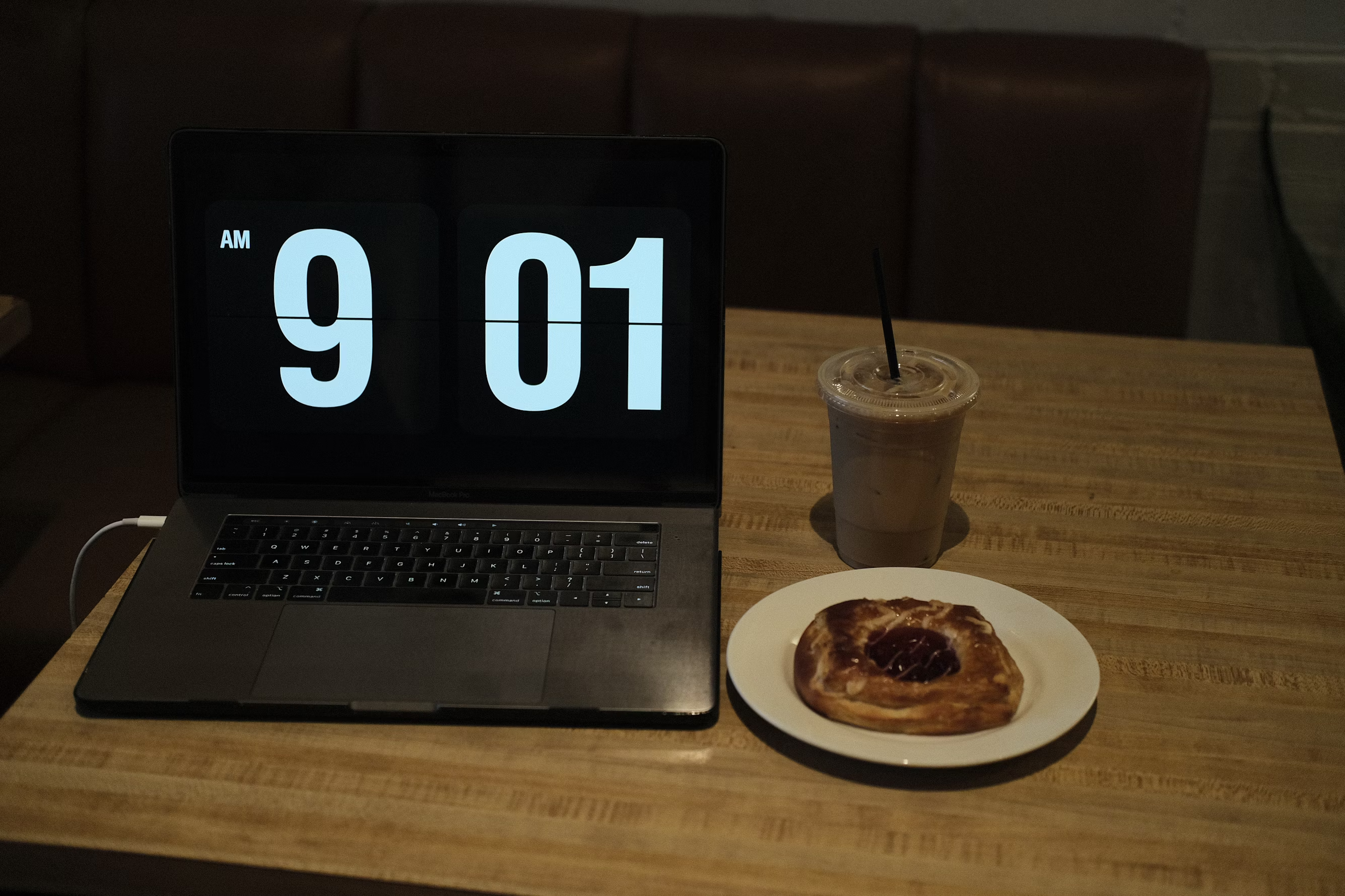


This image captures the theme of "reflections on time" by depicting a solitary workspace with a coffee cup and laptop,
representing the late-night hours often spent compensating for daytime distractions. The setup reflects my personal
struggle with productivity, symbolizing how time can feel elusive and fragmented. Through elements like the dim lighting
and focus on everyday objects, the image conveys a sense of introspection and the passage of time, as one contemplates
the balance between daily routines and the desire to make meaningful use of each moment.
This is my own refelection on time management
(#) 1.Simple Extra Emitters (spotlight, point light)
I implementd spotlight and point light. They both are delta lights.
They are implemented as surface.
PointLight is a delta emitter at a single point, radiating light equally in all directions.
It has no volume, represented by a very small bounding box for scene calculations.
SpotLight emits light within a cone which is just point light with area constraint.
We can tell from the image that these two delta lights create sharp shadows.
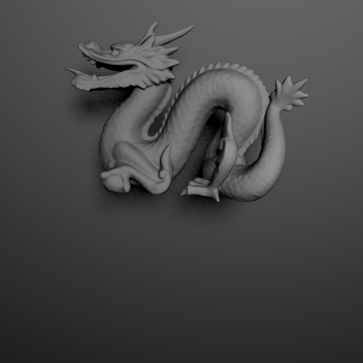
The quadlight creates a soft shadow.
(#) 2.Parallelization with Nanothread
code coordinate: scene.cpp
(#) 3.Smooth Conductor
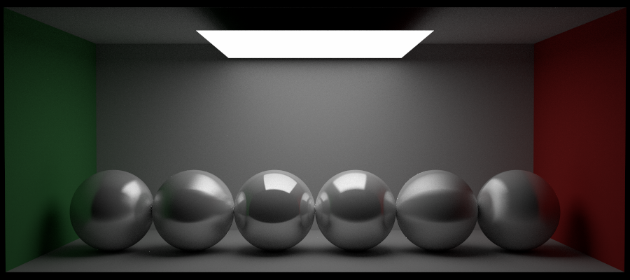
I implemented the smooth conductor material based on the Mitsuba renderer's documentation to model metallic surfaces.
Real (eta) and Imaginary (k) indices of refraction to simulate light interaction with metals..
For smooth conductors, we implemented perfect mirror reflection using the Fresnel conductor formula.
I only implemented the smooth one with roughness = 0.0f..
Here is results for three different conductor materials.
Gold (“eta”: [0.143119, 0.374957, 1.44248], “k”: [3.98316, 2.38572, 1.60322])
(#) 4.Ward Anisotropic
In the project, U implemented the Ward Anisotropic BRDF to model surfaces with directional roughness, like brushed
metal or fabric. The main idea was to split the reflection into two parts: diffuse and specular.
The Ward's BRDF is an elliptical Gaussian function in Ward's paper
$$f_r(\omega_i, \omega_o) = \frac{\rho_d}{\pi} + \frac{\rho_s}{4 \pi \alpha_x \alpha_y \sqrt{\cos \theta_i \cos
\theta_o}} e^{- \tan^2 \theta_h \left( \frac{\cos^2 \phi_h}{\alpha_x^2} + \frac{\sin^2 \phi_h}{\alpha_y^2} \right)}$$
First, we can separate the diffuse and specular components into 2 BSxF, and use Get BSDF to add them as 2 independent
surface properties of the material. In this way the probability of (wi,wo) below will be closer to the BRDF. Also we
pre-compute all constants in the BRDF, such as inverse ax and ay.
Anisotropic RoughConductor material validation
Tried to render the scene with the same alphaU and alphaV(0.15)as in the Reference-pdf paper.
From left to right: roughnessU/V are 0.6/0.05,0.05/0.6,0.1/0.03,0.03/0.1,0.05/0.2,0.2/0.05.
(#) 5.Photon Mapping
1.Two Photon Maps:
Global Photon Map: Standard photon mapping for general indirect lighting.
Caustics Photon Map: Stores light paths with specular interactions to capture caustics.
Illumination Calculation Pipeline:
2.Trace Path: From the camera until it hits the first non-specular surface.
Add Contributions:
Emission: Direct emission from light sources.
Direct Illumination: Calculated using Next Event Estimation (NEE).
Caustics: Estimated using the caustics photon map.
Indirect Illumination: Continue tracing until hitting a non-specular surface, then calculate from the global photon map.
bug I caused due to unnormalized caustics estimation.
gradually changing the parameters(initial radius), the bleeding effect becomes less and less.
(#) 6.Final Image
(#) 7.Reference
http://chiakailiang.org/project_ward/
https://www.graphics.cornell.edu/~bjw/wardnotes.pdf
https://github.com/yumcyaWiz/photon_mapping/tree/b5d25012ce0817e83c260f2a5b5a034ae0891561


